Your Binary subtractor circuit design images are available. Binary subtractor circuit design are a topic that is being searched for and liked by netizens now. You can Find and Download the Binary subtractor circuit design files here. Find and Download all royalty-free images.
If you’re searching for binary subtractor circuit design pictures information linked to the binary subtractor circuit design keyword, you have come to the ideal blog. Our site always provides you with suggestions for seeking the highest quality video and picture content, please kindly surf and locate more enlightening video articles and images that fit your interests.
Binary Subtractor Circuit Design. The half subtractor is used to subtract two binary. Submitted by Saurabh Gupta on January 23 2020. Unlike the Binary Adder which produces a SUM and a CARRY bit when two binary numbers are added together the binary subtractor produces a DIFFERENCE D by using a. The subtractor is one of the types of the combinational arithmetic circuit that generates an output which is the subtraction of two binary numbers.
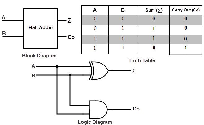 Binary Adder And Subtractor Circuits Half And Full Adder Subtractor From electronicshub.org
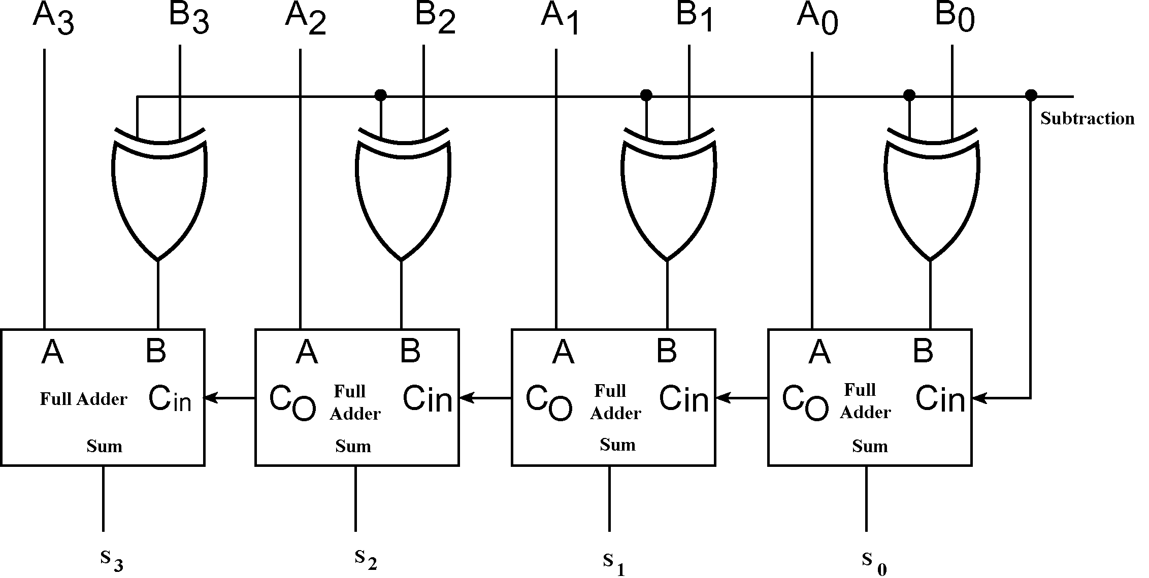
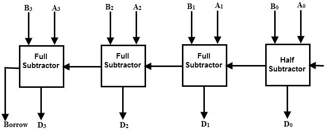
As their name implies a Binary Subtractor is a decision making circuit that subtracts two binary numbers from each other for example X Y to find the resulting difference between the two numbers. The two outputs D and. Binary arithmetic is an essential part of various digital systems. This circuit can be done with two half-Subtractor circuits. Till now we have already read in the previous articles about designing and uses of the basic form of adders and subtractors such as Half Adder Full Adder Half Subtractor and Full. The subtractor is one of the types of the combinational arithmetic circuit that generates an output which is the subtraction of two binary numbers.
It is the circuit in which subtraction of two bits is done by borrowing.
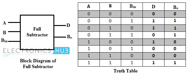
This circuit has three inputs and two outputsThe three inputs A B and Bin denote the minuend subtrahend and previous borrow respectively. Binary is a base-2 number system that uses two states 0 and 1 to represent a number. The two outputs D and. This circuit has three inputs and two outputsThe three inputs A B and Bin denote the minuend subtrahend and previous borrow respectively. This circuit can be done with two half-Subtractor circuits. As their name implies a Binary Subtractor is a decision making circuit that subtracts two binary numbers from each other for example X Y to find the resulting difference between the two numbers.
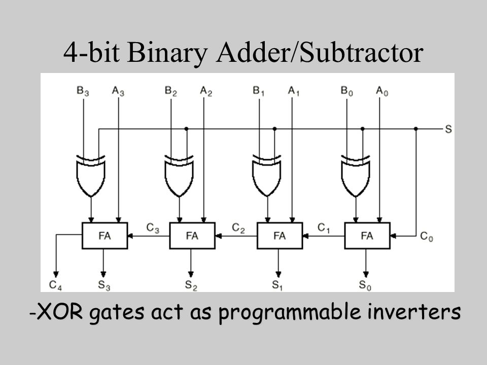 Source: slideplayer.com
A binary number is built the same way as we build the normal decimal number. Full Subtractor Circuit Diagram with Logic Gates. Unlike the Binary Adder which produces a SUM and a CARRY bit when two binary numbers are added together the binary subtractor produces a DIFFERENCE D by using a. The subtractor is one of the types of the combinational arithmetic circuit that generates an output which is the subtraction of two binary numbers. Binary is a base-2 number system that uses two states 0 and 1 to represent a number.
 Source: youtube.com
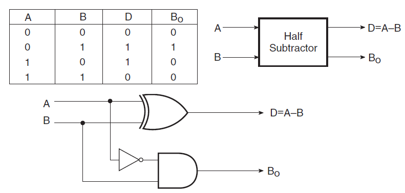
The two outputs D and. In this tutorial we are going to learn about the N-bit Parallel Adders 4-bit Binary Adder and Subtractor in Digital Electronics. The subtractor is one of the types of the combinational arithmetic circuit that generates an output which is the subtraction of two binary numbers. This circuit is used to subtract two binary values A and B that are both single bits. There are two inputs and two outputs on this device.
 Source: geeksforgeeks.org
In this tutorial we are going to learn about the N-bit Parallel Adders 4-bit Binary Adder and Subtractor in Digital Electronics. Till now we have already read in the previous articles about designing and uses of the basic form of adders and subtractors such as Half Adder Full Adder Half Subtractor and Full. There are two inputs and two outputs on this device. This circuit has three inputs and two outputsThe three inputs A B and Bin denote the minuend subtrahend and previous borrow respectively. Submitted by Saurabh Gupta on January 23 2020.
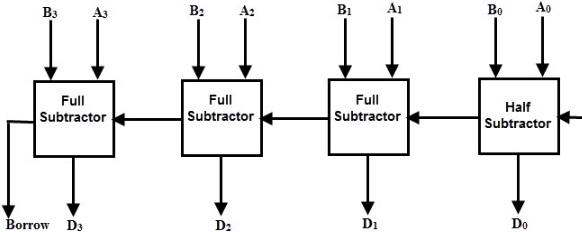 Source: watelectronics.com
Submitted by Saurabh Gupta on January 23 2020. It is the circuit in which subtraction of two bits is done by borrowing. This circuit has three inputs and two outputsThe three inputs A B and Bin denote the minuend subtrahend and previous borrow respectively. A full subtractor is a combinational circuit that performs subtraction of two bits one is minuend and other is subtrahend taking into account borrow of the previous adjacent lower minuend bit. There are two inputs and two outputs on this device.
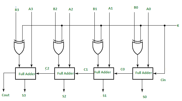 Source: geeksforgeeks.org
Till now we have already read in the previous articles about designing and uses of the basic form of adders and subtractors such as Half Adder Full Adder Half Subtractor and Full. Binary is a base-2 number system that uses two states 0 and 1 to represent a number. This circuit has three inputs and two outputsThe three inputs A B and Bin denote the minuend subtrahend and previous borrow respectively. This circuit can be done with two half-Subtractor circuits. The circuit diagram of the full subtractor using basic gates is shown in the following block diagram.
 Source: electronics-tutorial.net
Full Subtractor Circuit Diagram with Logic Gates. The subtractor is one of the types of the combinational arithmetic circuit that generates an output which is the subtraction of two binary numbers. Unlike the Binary Adder which produces a SUM and a CARRY bit when two binary numbers are added together the binary subtractor produces a DIFFERENCE D by using a. Binary is a base-2 number system that uses two states 0 and 1 to represent a number. There are two inputs and two outputs on this device.
 Source: electronics.stackexchange.com
In this tutorial we are going to learn about the N-bit Parallel Adders 4-bit Binary Adder and Subtractor in Digital Electronics. Till now we have already read in the previous articles about designing and uses of the basic form of adders and subtractors such as Half Adder Full Adder Half Subtractor and Full. In the initial half-Subtractor circuit the binary inputs are A and B. As their name implies a Binary Subtractor is a decision making circuit that subtracts two binary numbers from each other for example X Y to find the resulting difference between the two numbers. In this tutorial we are going to learn about the N-bit Parallel Adders 4-bit Binary Adder and Subtractor in Digital Electronics.
 Source: electronicshub.org
Through this article on Subtractors you will learn about half subtractors full subtractors with the truth tables circuit diagram and boolean expression. This circuit has three inputs and two outputsThe three inputs A B and Bin denote the minuend subtrahend and previous borrow respectively. Binary arithmetic is an essential part of various digital systems. Full Subtractor Circuit Diagram with Logic Gates. The half subtractor is used to subtract two binary.
 Source: electronicspost.com
A full subtractor is a combinational circuit that performs subtraction of two bits one is minuend and other is subtrahend taking into account borrow of the previous adjacent lower minuend bit. The subtractor is one of the types of the combinational arithmetic circuit that generates an output which is the subtraction of two binary numbers. The circuit diagram of the full subtractor using basic gates is shown in the following block diagram. Through this article on Subtractors you will learn about half subtractors full subtractors with the truth tables circuit diagram and boolean expression. Full Subtractor Circuit Diagram with Logic Gates.
 Source: electronicshub.org
Unlike the Binary Adder which produces a SUM and a CARRY bit when two binary numbers are added together the binary subtractor produces a DIFFERENCE D by using a. The two outputs D and. The subtractor is one of the types of the combinational arithmetic circuit that generates an output which is the subtraction of two binary numbers. Unlike the Binary Adder which produces a SUM and a CARRY bit when two binary numbers are added together the binary subtractor produces a DIFFERENCE D by using a. Full Subtractor Circuit Diagram with Logic Gates.
 Source: 101computing.net
A binary number is built the same way as we build the normal decimal number. There are two inputs and two outputs on this device. There are three inputs and two outputs. Full Subtractor Circuit Diagram with Logic Gates. Binary is a base-2 number system that uses two states 0 and 1 to represent a number.
 Source: electronics-tutorial.net
The half subtractor is used to subtract two binary. There are two inputs and two outputs on this device. The circuit diagram of the full subtractor using basic gates is shown in the following block diagram. Binary arithmetic is an essential part of various digital systems. This circuit can be done with two half-Subtractor circuits.
 Source: electronicshub.org
Unlike the Binary Adder which produces a SUM and a CARRY bit when two binary numbers are added together the binary subtractor produces a DIFFERENCE D by using a. Unlike the Binary Adder which produces a SUM and a CARRY bit when two binary numbers are added together the binary subtractor produces a DIFFERENCE D by using a. A binary number is built the same way as we build the normal decimal number. Binary arithmetic is an essential part of various digital systems. This circuit can be done with two half-Subtractor circuits.
 Source: sk.pinterest.com
This circuit is used to subtract two binary values A and B that are both single bits. Binary arithmetic is an essential part of various digital systems. A binary number is built the same way as we build the normal decimal number. Till now we have already read in the previous articles about designing and uses of the basic form of adders and subtractors such as Half Adder Full Adder Half Subtractor and Full. There are two inputs and two outputs on this device.
 Source: vlabs.iitb.ac.in
In this tutorial we are going to learn about the N-bit Parallel Adders 4-bit Binary Adder and Subtractor in Digital Electronics. A binary number is built the same way as we build the normal decimal number. The subtractor is one of the types of the combinational arithmetic circuit that generates an output which is the subtraction of two binary numbers. Unlike the Binary Adder which produces a SUM and a CARRY bit when two binary numbers are added together the binary subtractor produces a DIFFERENCE D by using a. The circuit diagram of the full subtractor using basic gates is shown in the following block diagram.
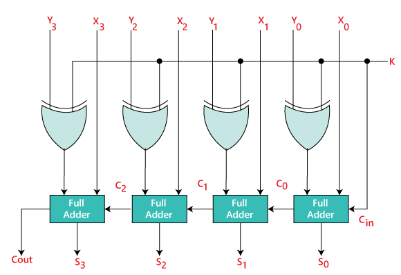 Source: javatpoint.com
A full subtractor is a combinational circuit that performs subtraction of two bits one is minuend and other is subtrahend taking into account borrow of the previous adjacent lower minuend bit. Binary arithmetic is an essential part of various digital systems. A binary number is built the same way as we build the normal decimal number. Unlike the Binary Adder which produces a SUM and a CARRY bit when two binary numbers are added together the binary subtractor produces a DIFFERENCE D by using a. The subtractor is one of the types of the combinational arithmetic circuit that generates an output which is the subtraction of two binary numbers.
 Source: wikiwand.com
As their name implies a Binary Subtractor is a decision making circuit that subtracts two binary numbers from each other for example X Y to find the resulting difference between the two numbers. This circuit can be done with two half-Subtractor circuits. Submitted by Saurabh Gupta on January 23 2020. This circuit is used to subtract two binary values A and B that are both single bits. The circuit diagram of the full subtractor using basic gates is shown in the following block diagram.
 Source: geeksforgeeks.org
The subtractor is one of the types of the combinational arithmetic circuit that generates an output which is the subtraction of two binary numbers. The subtractor is one of the types of the combinational arithmetic circuit that generates an output which is the subtraction of two binary numbers. In this tutorial we are going to learn about the N-bit Parallel Adders 4-bit Binary Adder and Subtractor in Digital Electronics. Till now we have already read in the previous articles about designing and uses of the basic form of adders and subtractors such as Half Adder Full Adder Half Subtractor and Full. A full subtractor is a combinational circuit that performs subtraction of two bits one is minuend and other is subtrahend taking into account borrow of the previous adjacent lower minuend bit.
This site is an open community for users to share their favorite wallpapers on the internet, all images or pictures in this website are for personal wallpaper use only, it is stricly prohibited to use this wallpaper for commercial purposes, if you are the author and find this image is shared without your permission, please kindly raise a DMCA report to Us.
If you find this site beneficial, please support us by sharing this posts to your preference social media accounts like Facebook, Instagram and so on or you can also save this blog page with the title binary subtractor circuit design by using Ctrl + D for devices a laptop with a Windows operating system or Command + D for laptops with an Apple operating system. If you use a smartphone, you can also use the drawer menu of the browser you are using. Whether it’s a Windows, Mac, iOS or Android operating system, you will still be able to bookmark this website.


