Your Airfoil design basics images are available in this site. Airfoil design basics are a topic that is being searched for and liked by netizens today. You can Download the Airfoil design basics files here. Download all free images.
If you’re looking for airfoil design basics images information connected with to the airfoil design basics topic, you have pay a visit to the ideal blog. Our site frequently gives you suggestions for downloading the highest quality video and image content, please kindly surf and locate more informative video articles and graphics that fit your interests.
Airfoil Design Basics. экраноплан screenglider is a vehicle that is able to move over the surface by gaining support from the reactions of the air against the surface of the earth or water. Welcome to Part 9 in the Fundamentals of Aircraft Design series. Just wanted to post this in here for anyone who doesnt use Fusion but is interested in how it works. Generally it is located at c4 where c is the chord length.
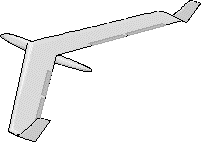
 Basic Design Of Flying Wing Models From mh-aerotools.de
You can copy Components between designs so if the body is in a component on its own select the component and Copy change to the other design right click on the canvas and select Paste New. A flat plate can generate lift but not as much as a streamlined airfoil and with somewhat higher drag. The process design basics are well understood for each of these processes independently but the simple descriptions above rarely apply as a single process requirement. The Autodesk Skill Builder is excellent you get a certificate at the end and its free. Plotting Angles of Attack Vs Drag Coefficient Transient State Plotting Angles of Attack Vs Lift Coefficient Transient State CONCLUSION. The point in airfoil where the lift can be supposed to be concentrated upon is called the centre of pressure.
An airfoil is a special shape that will produce lift when its moved through the air in one direction the shape can be seen if we look at the cross-section of a wing a lot of physics is involved in the study of these shapes to produce lift efficiently and there are lots of shapes that can be used for different scenarios not all are good for every situation so if you.
Basics of NACA 4 digit Airfoil The NACA airfoils are airfoil shapes for aircraft wings developed by the National Advisory Committee for Aeronautics NACA. Now we put it all together and run through a preliminary drag estimation of a new aircraft design. The point in airfoil where the lift can be supposed to be concentrated upon is called the centre of pressure. Typically it is designed to glide over a level surface usually over. An airfoil is a special shape that will produce lift when its moved through the air in one direction the shape can be seen if we look at the cross-section of a wing a lot of physics is involved in the study of these shapes to produce lift efficiently and there are lots of shapes that can be used for different scenarios not all are good for every situation so if you. Perform the required design work.
 Source: web.mit.edu
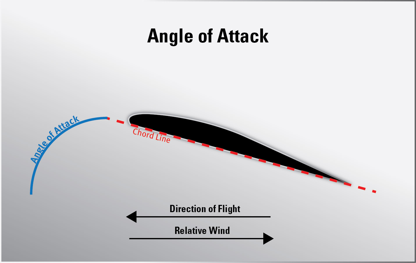
The Autodesk Skill Builder is excellent you get a certificate at the end and its free. Now we put it all together and run through a preliminary drag estimation of a new aircraft design. This site was built for high school and college students. Airfoil at different angles of attack angle between the approaching flow and airfoil chord line. Introduction to CFD Basics Rajesh Bhaskaran Lance Collins This is a quick-and-dirty introduction to the basic concepts underlying CFD.
 Source: sciencedirect.com
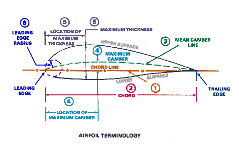
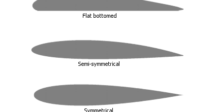
These laws govern airflow pres-. Even the efficient airfoil design shown. The con-cepts are illustrated by applying them to simple 1D model problems. Chord - Straight line distance between the leading and trailing airfoil edges. Generally it is located at c4 where c is the chord length.
 Source: pinterest.com
Basics of NACA 4 digit Airfoil The NACA airfoils are airfoil shapes for aircraft wings developed by the National Advisory Committee for Aeronautics NACA. These laws govern airflow pres-. Well invoke these concepts while performing case studies in FLUENT. The aerofoil is the foundation of wind turbine blade designs hence its optimisation goes a long way in achieving the three objectives of aerofoil design namely aerodynamic performance of the blade Noise control. Fan Laws - Set of laws that predict perfor-mance changes if one or more parameters are changed from one fan or operating condition to another.
 Source: aviationknowledge.wikidot.com
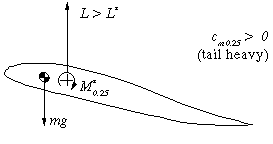
Typically it is designed to glide over a level surface usually over. Fan Laws - Set of laws that predict perfor-mance changes if one or more parameters are changed from one fan or operating condition to another. Now we put it all together and run through a preliminary drag estimation of a new aircraft design. Basics of NACA 4 digit Airfoil The NACA airfoils are airfoil shapes for aircraft wings developed by the National Advisory Committee for Aeronautics NACA. The point where the weight of the glider acts is termed as centre of gravity CG.
 Source: modelaviation.com
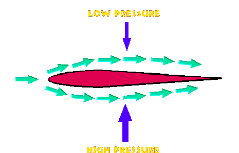
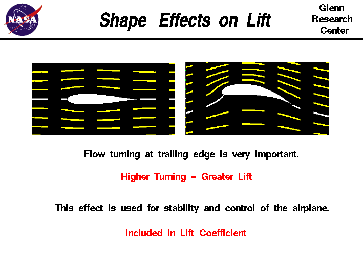
Index RocketModeler Interactive Simulator RocketNozzle Interactive Simulator Rocketry Guide and Activities. You can copy Components between designs so if the body is in a component on its own select the component and Copy change to the other design right click on the canvas and select Paste New. A ground-effect vehicle GEV also called a wing-in-ground-effect WIG ground-effect craft wingship flarecraft or ekranoplan Russian. Most simplified explanations follow one of two basic approaches based either on Newtons laws of motion or on Bernoullis principle. Index RocketModeler Interactive Simulator RocketNozzle Interactive Simulator Rocketry Guide and Activities.
 Source: defiantwings.blogspot.com
Most people with Inventor will also have a license of Fusion which youve probably not even installed. Introduction to CFD Basics Rajesh Bhaskaran Lance Collins This is a quick-and-dirty introduction to the basic concepts underlying CFD. Chord - Straight line distance between the leading and trailing airfoil edges. Most people with Inventor will also have a license of Fusion which youve probably not even installed. The shape of the NACA airfoils is described using a series of digits following the word NACA.
 Source: amazon.com
The process design basics are well understood for each of these processes independently but the simple descriptions above rarely apply as a single process requirement. The Autodesk Skill Builder is excellent you get a certificate at the end and its free. The aerofoil is the foundation of wind turbine blade designs hence its optimisation goes a long way in achieving the three objectives of aerofoil design namely aerodynamic performance of the blade Noise control. Plotting Angles of Attack Vs Drag Coefficient Transient State Plotting Angles of Attack Vs Lift Coefficient Transient State CONCLUSION. Airfoil at different angles of attack angle between the approaching flow and airfoil chord line.
 Source: aircraftspruce.com
Even the efficient airfoil design shown. Generally it is located at c4 where c is the chord length. Introduction to CFD Basics Rajesh Bhaskaran Lance Collins This is a quick-and-dirty introduction to the basic concepts underlying CFD. Plotting Angles of Attack Vs Drag Coefficient Transient State Plotting Angles of Attack Vs Lift Coefficient Transient State CONCLUSION. You can copy Components between designs so if the body is in a component on its own select the component and Copy change to the other design right click on the canvas and select Paste New.
 Source: youtube.com
Perform the required design work. Perform the required design work. The point in airfoil where the lift can be supposed to be concentrated upon is called the centre of pressure. The Autodesk Skill Builder is excellent you get a certificate at the end and its free. The shape of the NACA airfoils is described using a series of digits following the word NACA.
 Source: mh-aerotools.de
Chord - Straight line distance between the leading and trailing airfoil edges. In steady-state simulation we observed that the values for Drag force P x and Lift force P y are fluctuating a lot and are not getting converged at the end of the steady-state simulationHence there is a need to perform transient state. Happily for us these model-problem. To sum it all the design considerations are numerous and at times conflicting leading to the need for an intelligent compromise. Perform the required design work.
 Source: rclibrary.co.uk
The point where the weight of the glider acts is termed as centre of gravity CG. Basics of NACA 4 digit Airfoil The NACA airfoils are airfoil shapes for aircraft wings developed by the National Advisory Committee for Aeronautics NACA. Index RocketModeler Interactive Simulator RocketNozzle Interactive Simulator Rocketry Guide and Activities. Plotting Angles of Attack Vs Drag Coefficient Transient State Plotting Angles of Attack Vs Lift Coefficient Transient State CONCLUSION. The point in airfoil where the lift can be supposed to be concentrated upon is called the centre of pressure.
 Source: aerospaceweb.org
For weight balance the centre of gravity must coincide with the centre of pressure. Most simplified explanations follow one of two basic approaches based either on Newtons laws of motion or on Bernoullis principle. Airfoil at different angles of attack angle between the approaching flow and airfoil chord line. These laws govern airflow pres-. In steady-state simulation we observed that the values for Drag force P x and Lift force P y are fluctuating a lot and are not getting converged at the end of the steady-state simulationHence there is a need to perform transient state.
 Source: grc.nasa.gov
Welcome to Part 9 in the Fundamentals of Aircraft Design series. Perform the required design work. Basics of NACA 4 digit Airfoil The NACA airfoils are airfoil shapes for aircraft wings developed by the National Advisory Committee for Aeronautics NACA. The aerofoil is the foundation of wind turbine blade designs hence its optimisation goes a long way in achieving the three objectives of aerofoil design namely aerodynamic performance of the blade Noise control. Chord - Straight line distance between the leading and trailing airfoil edges.
 Source: aerospaceweb.org
Well invoke these concepts while performing case studies in FLUENT. Explanation based on flow deflection and Newtons. For weight balance the centre of gravity must coincide with the centre of pressure. Happily for us these model-problem. Just wanted to post this in here for anyone who doesnt use Fusion but is interested in how it works.
 Source: flitetest.com
Airfoil at different angles of attack angle between the approaching flow and airfoil chord line. The con-cepts are illustrated by applying them to simple 1D model problems. Plotting Angles of Attack Vs Drag Coefficient Transient State Plotting Angles of Attack Vs Lift Coefficient Transient State CONCLUSION. The shape of the NACA airfoils is described using a series of digits following the word NACA. Most simplified explanations follow one of two basic approaches based either on Newtons laws of motion or on Bernoullis principle.
 Source: cfinotebook.net
A ground-effect vehicle GEV also called a wing-in-ground-effect WIG ground-effect craft wingship flarecraft or ekranoplan Russian. Happily for us these model-problem. These laws govern airflow pres-. The aerofoil is the foundation of wind turbine blade designs hence its optimisation goes a long way in achieving the three objectives of aerofoil design namely aerodynamic performance of the blade Noise control. For weight balance the centre of gravity must coincide with the centre of pressure.
 Source: airshaper.com
Most people with Inventor will also have a license of Fusion which youve probably not even installed. If the body is in a component with other bodies youll have to use Create components from bodies first. In the previous posts we have covered the fundamentals of flight studied the wing fuselage and empennage and have been introduced to aerodynamic lift drag and moment coefficients. Now we put it all together and run through a preliminary drag estimation of a new aircraft design. A ground-effect vehicle GEV also called a wing-in-ground-effect WIG ground-effect craft wingship flarecraft or ekranoplan Russian.

Generally it is located at c4 where c is the chord length. Now we put it all together and run through a preliminary drag estimation of a new aircraft design. The process design basics are well understood for each of these processes independently but the simple descriptions above rarely apply as a single process requirement. If the body is in a component with other bodies youll have to use Create components from bodies first. An airfoil is a special shape that will produce lift when its moved through the air in one direction the shape can be seen if we look at the cross-section of a wing a lot of physics is involved in the study of these shapes to produce lift efficiently and there are lots of shapes that can be used for different scenarios not all are good for every situation so if you.
This site is an open community for users to do submittion their favorite wallpapers on the internet, all images or pictures in this website are for personal wallpaper use only, it is stricly prohibited to use this wallpaper for commercial purposes, if you are the author and find this image is shared without your permission, please kindly raise a DMCA report to Us.
If you find this site adventageous, please support us by sharing this posts to your favorite social media accounts like Facebook, Instagram and so on or you can also bookmark this blog page with the title airfoil design basics by using Ctrl + D for devices a laptop with a Windows operating system or Command + D for laptops with an Apple operating system. If you use a smartphone, you can also use the drawer menu of the browser you are using. Whether it’s a Windows, Mac, iOS or Android operating system, you will still be able to bookmark this website.


